
lasciate un messaggio
Se siete interessati ai nostri prodotti e desiderate maggiori informazioni, lasciate un messaggio qui; vi risponderemo il prima possibile.


Whether you are a regional Internet Service Provider (ISP) expanding broadband to rural communities or a network architect managing a hyperscale data center, physical fiber management dictates your network's long-term reliability. At the absolute core of this physical infrastructure sits the Optical Distribution Frame (ODF). Unlike standard IT racks that merely hold servers, an ODF is a specialized mechanical ecosystem designed exclusively to terminate, splice, route, and protect fragile optical fibers. As global fiber rollouts accelerate to meet the relentless bandwidth demands of 5G networks and FTTH (Fiber to the Home) expansions, understanding how to properly configure and scale your ODF architecture is no longer optional. It has become a critical engineering requirement for minimizing optical insertion loss, managing cable congestion, and preventing costly network downtime during routine maintenance.
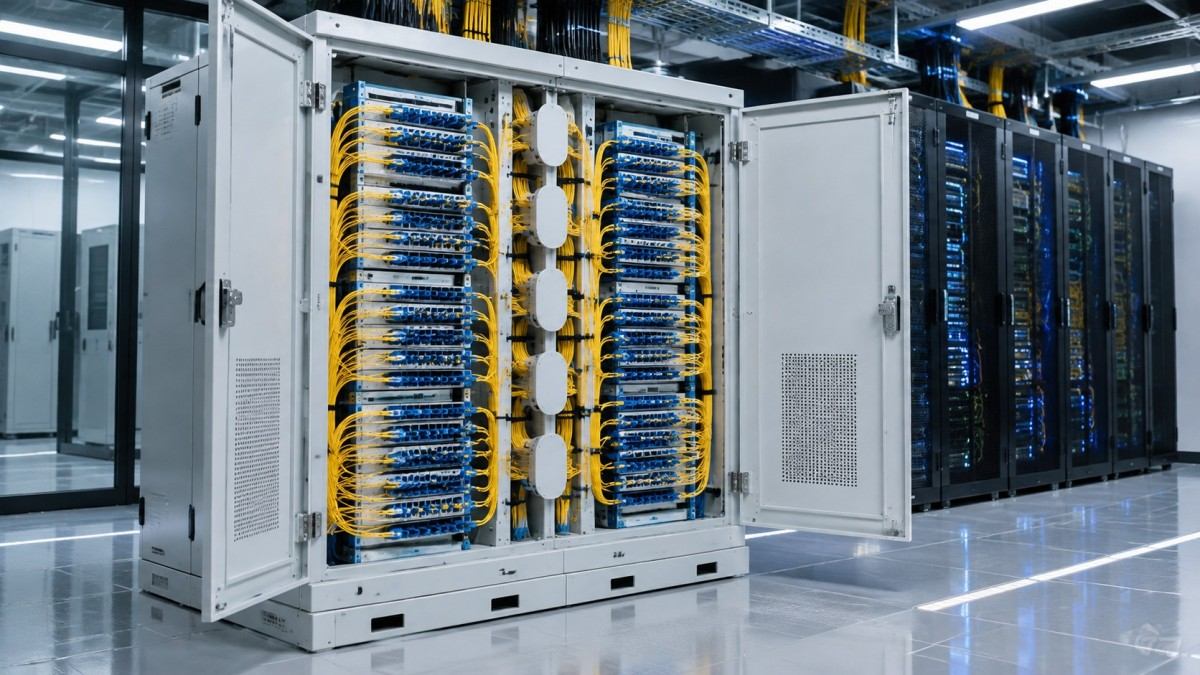
It is a common misconception to view an ODF as just a metal cabinet. In reality, it serves as the critical demarcation point where heavy, rigid outside plant (OSP) cables transition into flexible indoor patch cords that connect to your active transmission equipment, such as optical switches and transceivers. A professional ODF system executes three non-negotiable functions to maintain optical budget integrity:
The physical layout of telecommunication rooms varies vastly across different geographic regions due to real estate costs, local building codes, and network density requirements. Therefore, selecting the right ODF architecture depends entirely on your specific deployment environment:
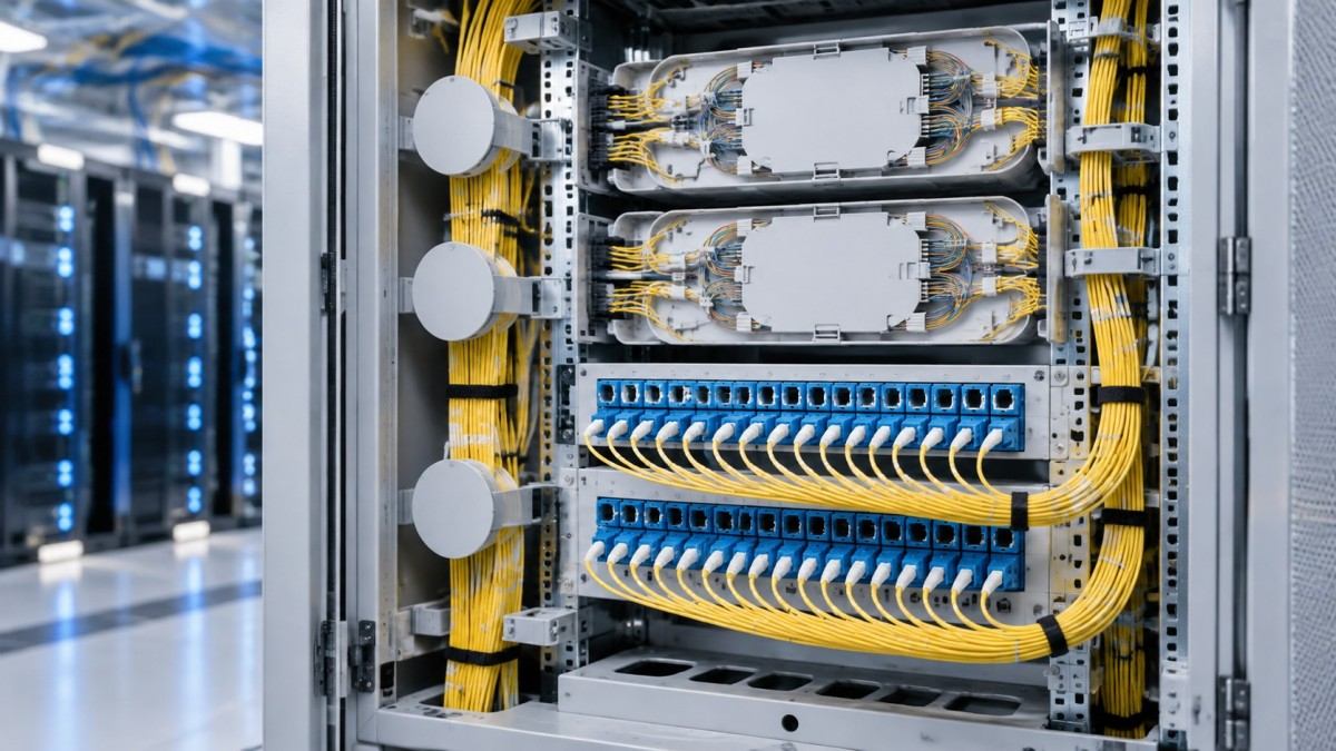
To ensure future scalability and avoid premature infrastructure bottlenecks, network planners should strictly evaluate their current fiber counts and factor in a minimum 30% to 40% expansion margin before purchasing. Refer to the configuration guide below to align your hardware choice with your specific project requirements.
| ODF Architecture Type | Typical Core Capacity | Termination Methodology | Primary Application Scenario |
|---|---|---|---|
| Wall-Mounted Enclosure | 12 to 96 Cores | Pigtail Fusion Splicing / Direct Patching | FTTB (Fiber to the Building), Edge Computing sites |
| Standard Rack-Mount (1U-4U) | 48 to 288 Cores | Manual Field Splicing (Slide-out trays) | Regional Central Offices, University Campus Networks |
| High-Density Modular Frame | 144+ Cores per 1U (Scaling to thousands) | Pre-terminated MPO/MTP Cassettes | Hyperscale Data Centers, 5G Core Distributions |
Conclusion: Investing in the right Optical Distribution Frame secures the physical foundation of your entire telecommunications network. By prioritizing robust cable management, appropriate geographic sizing, and strict bend-radius protection, you ensure that your fiber infrastructure remains organized, resilient, and fully prepared for the next generation of bandwidth upgrades.
Q1: What is the exact difference between an ODF and a standard network patch panel?
A: While a standard patch panel simply houses adapters to connect two active cables (like RJ45 copper ports), an ODF is a comprehensive mechanical system. It integrates secure splice enclosures for permanent bare-fiber fusion, dedicated slack storage mechanisms, and advanced physical routing guides designed specifically to protect glass fibers from tension, crushing, and macro-bending.
Q2: Can I mix different fiber optic connector types within the same ODF chassis?
A: Yes. Modern modular ODFs are highly versatile. By utilizing interchangeable front adapter plates or plug-in cassettes, network technicians can easily mix LC, SC, FC, and high-density MPO connections within the exact same rack space. This flexibility allows for seamless integration of mixed-use network architectures and legacy equipment upgrades.
Q3: How does a high-density ODF prevent optical signal loss (macro-bending)?
A: High-density frames manage massive amounts of cables by employing specialized articulating cable managers, radius-control routing spools, and angled patch panels. These structural guides mechanically force the fiber patch cords to route at safe, predetermined angles, ensuring the bend radius never exceeds the critical threshold (typically 30mm) that causes signal attenuation.
lasciate un messaggio
Scan to Wechat :

Scan to WhatsApp :